Moshe Daniel's Moe-Joe©©and Joe Cell Pages
Archives of Instructional Videos - Contain lots of useful Moe-Joe cell information
Archives of Philosophical, Results, and Design Videos - Also contain lots of useful Moe-Joe cell information
Archives of Instructional Videos for Charging and Assembly - Contain lots of useful Moe-Joe cell information
Archives of Moe-Joe Cell Images
note: All of the knowledge shared on
these pages is under Collective Copyright ©© - click
here to find out more about Collective Copyright (a
part of EveryNationLand / Nutopia)
| Moe-Joe Cell
Videos and Pics |
 |
| Joe Cell Pics
|
 |
| Moshe
Daniel's
Healing Chamber
Shooter Box extraordinaire
featuring two Moe-Joe cells as the source, crystals, orgonite, magnets |
 |
| Moshe
Daniel's Healing
Staff |
 |
| Moshe's other work - David House Productions
(Kabbalah, Alchemy, Naturopathic medicine, Homeopathy, Astrology, Music) |
 |
| Links to Other
Joe Cell Sites
about the Joe Cell - link: http://www.joecell.info/index.html
My friend David Jacques's site in French and other very good links from here, like
very well organized updates to the Joe Cell from Alex Schiffer, etc.: http://divadjac.googlepages.com/libre
http://www.joecellenergy.com/
http://scene.org/~esa/merlib/joecell/joecellinfo.html Lots of
excellent videos on the Joe Cell.
http://www.joecelldevices.com/ |
|
Former Instructional Videos - Now Archived due to Improved and Simplified Design
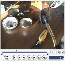
Instructional Videos 1) Kit Assemblies 2) Car Installation -
Discussions / Articles - Car Kit Assembly
TInstructional Videos - Car Cell and Charging Vat Assembly
Car Kit Assembly for Installation
Method 1 (for vacuum or air intake without bismuth core) - HALF-CELL approach -
WATCH VIDEO to accompany this information (but note - this is no longer the recommended approach - it is just for experimental purposes, as it emulates the Joe cell more - but the power of the Moe-Joe cell lives in its completed SPHERICAL FORM)
1) Assemble the bottom half of a cell - Take a 2" hemisphere and put a rod through the centre hole so that the rod is just sticking into the inner part of the 2" sphere. Place a NYLON nut onto the small portion sticking into the 2" and then place a stainless steel nut on the outside, and screw down and then secure. Assemble the rest of the 3", 4", and 5" and then tighten the outer 5" nut to the inner 2" nut.- When you tighten the nut on the outside of the 5" with the nut on the inside of the 2" make certain that you use goop or silicon gel or some sealant to seal off the hole and the nut and bolt on the outside of the 5" since this will be serving as our car kit and must be sealed. You should use the bottom 5" with the lip around the equator and the 3/8" on the bottom centre. Now we have half a cell assembled. Take only the upper 5" which has the larger hole on the top and the hole on the side for the +ve electricity bolt and connect the +ve bolt and an aluminum tube connector at this point if you are using one. Wait until the sealant / goop used dries and the connector is solidly attached. Once it is dried and hardened, place the upper 5" hemisphere over the lower half assembled cell and seal around the equator with goop, silicon gel, or sikaflex, or your favourite sealant. Then, when you fill the cell, fill up the cell only halfway, so that the water is slightly, very slightly only, below the tops of the hemispheres. This is the best method for assembly of the cell using the vacuum or air intake method. If you are using a bismuth core with this method, make sure you remove the nylon bolt and just use the stainless bolt - then make sure the bismuth core is centered in the center of the hemisphere, as if it would be centred in the midth of the 2" sphere if it was a completed sphere. Then secure the nylon nut on the inside of the 2" and the stainless nut on the outside of the 2".
Now you can charge your car kit outside of the car following Pepi's method or other charging methods below. Make sure not to overcharge, as you will mess up the cell and have to take it apart, clean it and start over. Less is more in this case.
Car Installation Videos
Land Rover Discovery 2 - 2001
This Video Contains instructions on how to assemble the Moe-Joe Cell and Install into the Car via VACUUM intake, and also demonstrates how to get under the car and locate the catalytic converter and the O2 sensors. (note: in this video, we chose a method we are no longer employing the use of - We hooked the two rear O2 sensors together and then we also hooked up the front two O2 sensors together - Also, we are no longer using the Cell Guardian. It DOES NOT WORK - it is a scam. We are sorry if this has misled anyone. The good results we got were exclusively from the Moe-Joe working, and NOT the Cell Guardian... click here for more on this).
Moe-Joe Cell Car Installation in Land Rover - Instructional Video |
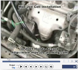
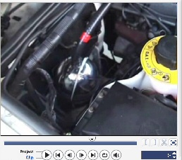
Honda Accord 2001
This short video demonstrates a Moe-Joe cell installed in a 2001 Honda Accord right in between the radiator fans and the exhaust. The cell stayed cool to the touch.
Note: I say in the end of the video - the only oxygen sensor it has - was my mistake - there is another one right above where the exhaust is - found it just after shooting this video. You can see it just to the left of the aluminum cover over the top of the exhaust.
Moe-Joe Cell Car Installation in Honda Accord 2001 - Instructional Video |
Note - If you are not using a bismuth core then set up your cell as follows (this method will require extra spacers for the extra nuts needed, or the extra nuts will be supplied with your kit if you did not purchase a bismuth core) -
WATER-ONLY CORE METHOD of THE MOE-JOE CELL ASSEMBLY
Click here to watch videos of these assemblies -
Part 1 - Part 2
PART A ) For the bottom half of the Moe Joe cell - take a 2" hemisphere and put a rod through the centre hole so that the rod is just sticking into the inner part of the 2" sphere. Place a NYLON nut onto the small portion sticking into the 2" and then place a stainless steel nut on the outside, and screw down and then secure. Assemble the rest of the 3", 4", and 5" and then tighten the outer 5" nut to the inner 2" nut.
PART B) Repeat with the other half - Use the nylon bolt this time and use a nylon nut inside and outside the 2"securing the nylon bolt onto the 2" - then assemble the 3", 4", and 5" and tighten the outer 5" nut with the inner 2" nut.
PART C ) Now Place the bottom half of the cell, which should have a nice sized length of stainless steel bolt coming through the bottom - place this through the hole in the bottom of your glass jar. Use goop or silicon gel or some sealant at the bottom and place a washer and then another nut on the outside of the glass jar, and tighten the nut both on the outside and the inside of the 2" - this will secure the entire half assembly very tightly with the glass jar. Then take your upper half of the cell and slot it onto the lower half.
This is all that is needed -no glueing or securing of the two halves is needed because we are only using this for the charging process.

Setting up Your Car Kit (for prepping water and for installation in car)
(note - this is no longer the recommended approach - it is just for experimental purposes, as it emulates the Joe cell more - but the power of the Moe-Joe cell lives in its completed SPHERICAL FORM)
Method 1 (for vacuum or air intake without bismuth core) - HALF-CELL approach - Assemble the bottom half of a cell using PART A the method right above called Water-Only Core Method - When you tighten the nut on the outside of the 5" with the nut on the inside of the 2" make certain that you use goop or silicon gel or some sealant to seal off the hole and the nut and bolt on the outside of the 5" since this will be serving as our car kit and must be sealed. You should use the bottom 5" with the lip around the equator and the 3/8" on the bottom centre. Now we have half a cell assembled. Take only the upper 5" which has the larger hole on the top and the hole on the side for the +ve electricity bolt and connect the +ve bolt and an aluminum tube connector at this point if you are using one. Wait until the sealant / goop used dries and the connector is solidly attached. Once it is dried and hardened, place the upper 5" hemisphere over the lower half assembled cell and seal around the equator with goop, silicon gel, or sikaflex, or your favourite sealant. Then, when you fill the cell, fill up the cell only halfway, so that the water is slightly, very slightly only, below the tops of the hemispheres. This is the best method for assembly of the cell using the vacuum or air intake method. If you are using a bismuth core with this method, make sure you remove the nylon bolt and just use the stainless bolt - then make sure the bismuth core is centered in the center of the hemisphere, as if it would be centred in the midth of the 2" sphere if it was a completed sphere. Then secure the nylon nut on the inside of the 2" and the stainless nut on the outside of the 2".
Now you can charge your car kit outside of the car following Pepi's method or other charging methods below. Make sure not to overcharge, as you will mess up the cell and have to take it apart, clean it and start over. Less is more in this case.
Method 2 (for blind plug only with or without bismuth core) - WHOLE CELL APPROACH - Without the bismuth core - assemble the cell exactly as per the instructions above following the Water-Only Core Method of the Moe-Joe Assembly - It is recommended that you use TWO stainless steel bolts (which requires the Xtra spacers option) instead of using the nylon bolt, so that the negative electricity can be brought through the bottom of the cell from the negative of the battery, and also, so that the bolt coming up from the 2" and through the top of the cell can have a wire placed on it, that will be carried along the inside of the transfer tube and place in direct contact with the negatively grounded engine. Make sure that when you form the bottom half of the cell, you use goop / silicon gel / some sealant to seal the bottom of the cell off, and secure the outer nut on the 5" with the inner nut on the 2". Once you get the two hemispheres fully asssembled, place them together, slot firmly in place, and then use goop / silicon gel / sealant around the equator - this will hold the two hemispheres together very firmly. Make sure, when using the blind plug method - that before sealing the two hemispheres together, that the wire being transferred to the engine block / head, is well fastened and shrinkwrapped or sealed to the cathode bolt coming up through the whole in the upper 5" and that the aluminum connector is nicely fastened to the top hole on the upper 5". Make sure to measure the distance from where the cell will be installed to the engine block where you will install the blind plug - or you can use extra wire and cut it to measure later, but the transfer tube must be measured precisely.
Fill the cell all the way up to the top.
Now you can charge your car kit outside of the car following Pepi's method or other charging methods below. The aluminum connector, being sealed to the top, provides a recepticle at the top for any water that overflows from the cell during charging due to displacement of the water from gas production. Make sure not to overcharge, as you will mess up the cell and have to take it apart, clean it and start over. Less is more in this case.
Moshe's "Moe-Joe"
Spherical Joe Cell design -
Thursday, August 30, 2007
note: All of the knowledge shared on
these pages is under Collective Copyright ©© - click
here to find out more about Collective Copyright (a
part of EveryNationLand / Nutopia)
NEW and IMPROVED Design
How to Assemble and Build the Moe-Joe - Video

Additional notes on improved design:
1) There is some debate about where to apply the +ve
and the -ve - currently, many of us in the Northern Hemisphere have decided that
it is important to apply the +ve to the inner sphere and the -ve to the outer.
This seems to comply with the opposite electromagnetic field as the Southern
Hemisphere, and therefore, the attributes of Male and Female would be +ve for
Female and -ve for Male, since the female MUST be on the inside, and the male on
the outside.
2) If possible, try to get a 4" stainless steel
non-magnetic 1/4" threaded the whole way bolt. It is easier to work with than
the 3" when using a 5" outer sphere. If you just do a 3 sphere Moe-Joe design,
then the 3" bolt is fine.
3) Not shown in this video is another possible idea
that i have tried - it involves having a hollow threaded tube to pass the
cathode bolt (the bolt that runs all the way into the inner sphere) - what you
would do, is drill a large whole on the opening at the top - insert your
threaded hollow tube - diameter must be at least 3/8" - secure your threaeded
tube with a nut on inside and out, then you pass your INSULATED cathode bolt up
through the hollow threaded tube, and make sure it sticks out the top. Then,
secure a nut at the end of the cathode bolt, making sure it is not insulated in
its length that sticks out beyond the hollow threaded tube - and secure it. Use
plastic nut. This way, the magnetic field of the wires applied to the Moe-Joe
are already in alignment. (make sure the hollow threaded tube is stainless steel
- i used brass and it corroded pretty quickly)
May 2007 - this was the old Method of
Assembly!!
Easter
Wednesday, October 17, 2007

I have uploaded a
short 2 min video demonstrating some very exciting and clear
observations -
there is a
comparison of the difference with the non-magnetic (316L)
stainless only Moe-Joe versus a somewhat magnetic Moe-Joe which
has 304 stainless in it.
The difference may
be between 304 and 316, or simply the fact that the 304 is
magnetic. |
Monday, April 02, 2007

Demonstration of the Moe-Joe in action - this is a
new Moe-Joe cell design, with only 3 spheres, and completely
non-magnetic. |

Demonstration of the Moe-Joe in action - this is
the older design, though it is assembled better, and this stainless
steel is slightly magnetic. |

check out this video
demonstrating a clear Figure 8 pattern immerging after a filtering with
blue shop towels by Kimberly-Waverly |
|
| |
|
Saturday, June 24th, 2006
this was the old assembly process. I am using better steel now, and seeking the
completely non-magnetic Moe-Joe experience. The new Moe-Joe I am using, is only
3 spheres - 4", 3", and 2" and completely NON-magnetic. The energy it emits in
the area is very peaceful, calming, and energizing.

2", 3", 4", and 5" diameter 316 stainless.
(the 2" and 3" are practically non-magnetic, but both the 4" and the 5" will
stick a rare-earth magnet. Not ideal, but doesn't seem to affect the charging of
the water process)
| This video is dedicated to
Walt, who had wanted to see the Moe-Joe in action, charging. It is low
quality, but you can really get a sense of the foam that is being
created at around the 45 second point, when I show a side-shot of the
foam "mound." |
 |
Saturday, June 24th, 2006
| I have just updated the design of the Moe-Joe. It
includes very little loss of magnetic field. The entire inner sphere is
surrounded by the outer sphere. The electromagnetic field is almost perfect,
with the exception of a few holes for bubble exit and water circulation. The
pictures shown below dated May 8th are of an older design and have a gap between the
hemispheres, and also use aluminum tape. The new design has no gap, or a very
very small one, and I am now using stainless steel tape, which is non-magnetic
and very strong.
|
 |
CATHODE
Cathode going through holes
drilled into stainless spheres. The cathode is contacting the outer part
of the inner sphere, and on the inside, is insulated with a rubber ring.
The head of the bolt is also insulated with a small white plastic cap,
as also seen covering the head of the bolt on the anode below. |
 |
ANODE
Here the other hemispheres are mounted
together with Buna. I only use a dab of goop in the Buna as shown in the
center of the 3" sphere shown here. The anode is contacting the inner
surface of the outer sphere and is insulated from the outer surface. I
put a little plastic cap on the head to prevent head of anode bolt from
reacting with the -ve inner sphere. |
 |
| Here is the entire Moe-Joe
Improved assembly docked. The stainless steel tape was not holding in
the water, so I cut two pieces to do the entire circumference. This way,
they will hold. The cathode bolt is screwed into a 1/4" threading which
is insulated with shrink wrap. The other end of the 1/4" threading has a
bolt coming out of the bottom of the glass, which will receive the
negative electricity. |
 |
| Please check out this video of
the Moe-Joe Surface tension - you will see, as I dip the spoon into the
water, that the entire surface responds, both when the spoon goes in and
when it comes out. Also, note the jelly-like consistency of the water.
It is a little tough to see, but if you watch closely, you will catch
it. |
|
| Have you ever seen water behave
in this fashion? (when it wasn't frozen, that is) |
 |
May 8th 2006
Assembly of the Moe-Joe Cell
| The three outer hemispheres are now BUNA-N'd together
(no glue), and I leave the inner sphere loose until the cathode is
properly connected.
Note: I do place a piece of 1/2" cut Buna on the bottom of the
hemisphere where I am mounting another hemisphere - it is there only in
place until the other three pieces of Buna are in place, and then i take
out the bottom piece, as it is no longer needed. |
 |
|
The inner sphere has a hole drilled into it so that the bolt carrying the -ve
charge comes up through the bottom, through the holes in the three outer spheres
and connects with the outside of the inner sphere. The bolt actually goes
through to the inside, but is insulated, not touching, electrically, the inner
surface of the inner sphere, and the head of the bolt has a plastic hat on which
is gooped and sealed, so not in contact with the water.
|
 |
| Once this is done, I attach the second hemisphere of the inner sphere to the
one with the bolt, and i tape them together using aluminum tape. I won't drink
too much of this water, due to the use of aluminum, but results are
still good with this setup. |
 |
| |
Then i use BUNA-N pieces to hold the inner sphere to the other hemispheres,
and then I close them together as close as possible - due to the cathode bolt
coming through the bottom and the bottom to the positive outer sphere (seen in
pic below) the hemispheres will stay slightly open and apart, allowing the gas
to escape. It usually does so in steady gas production and every once in a while
will yield big burps of bubbles. Once the anode is bolted in, |
| notice the setup of the anode - the electricity is only contacting the inner
surface of the outer sphere and there is a rubber ring where the bolt is
attached on the outer surface - this helps physically secure the entire setup
and holds the Moe-Joe in place. Then i use two pieces of aluminum tape to hold
the cell together, and i apply a small piece of that tape in reverse on the
sticky side to ensure passing of the current across the hemisphere gap. If i
didn't add this extra piece of tape, the aluminum glue on the sticky side would
not conduct across the gap, and that is what we want. |
 |
| |
|
| |

The Moe-Joe Cell Assembled
and Submerged
|
| |
In the near future, I will close all the spheres, and have the bolts
running through a hole drilled into each of the spheres -I would like to
see how this affects the performance of the Moe-Joe. Oh, and he he, yes,
there will be holes for the gas to escape. |
More Moe-Joe Pics
| May 27th 2006: This picture is
particularly interesting - notice the very white quality of the water
surrounding the bubbles. I would describe it best as milky white. It was
like pure cream, even more so than the pic below of May 24th. 1 hour
later, around half the bubbles seen in this picture are still present on
the water and that is while the water and cell are uncovered.
|
 |


Milky white close-up, of many tiny bubbles |
May 24th 2006: This result is even better than that achieved on May 16th.
This is the first charge after the cooking and filtering, but only for 10
minutes this time.

May 16th 2006
After applying Bernie's Cooking method, I may even have achieved stage 3 here
with the Moe-Joe Cell! These are the best results i have seen to date with the
Moe-Joe Cell with no electrolyte!!

Go to David House Productions